|
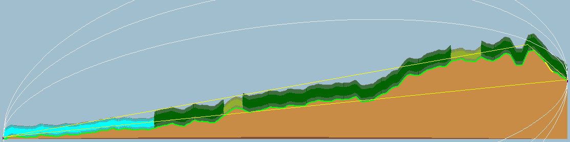
After creation of a new Link the result is displayed in the Link Evalusation Window.
 |
| Radio link study 3 |
PI1APA (1)
| Latitude |
52.201564 |
° |
| Longitude |
5.992506 |
° |
| Ground elevation |
13.01 |
m |
| Antenna height |
2.00 |
m |
| Azimuth |
255.44 |
° |
| Tilt |
0.21 |
° |
|
(2) PI1APK
| Latitude |
52.176202 |
° |
| Longitude |
5.833987 |
° |
| Ground elevation |
64.44 |
m |
| Antenna height |
2.00 |
m |
| Azimuth |
75.31 |
° |
| Tilt |
-0.31 |
° |
|
Radio system
| TX power |
20.000 |
W |
| TX line loss |
3.00 |
dB |
| TX antenna gain |
6.00 |
dBi |
| RX antenna gain |
2.00 |
dBi |
| RX line loss |
0.50 |
dB |
| RX sensitivity |
0.50 |
μV |
|
Propagation
| Free space loss |
96.65 |
dB |
| Obstuction loss |
46.81 |
dB |
| Forest loss |
2.86 |
dB |
| Urban loss |
5.98 |
dB |
| Statistical loss |
5.72 |
dB |
| Total path loss |
158.02 |
dB |
|
Performance
| Distance |
11.168 |
km |
| Frequency |
146.000 |
MHz |
| Equivalent Isotropically Radiated Power |
39.905 |
W |
| System gain |
160.53 |
dB |
| Required reliability |
70.000 |
% |
| E field |
8.49 |
dBμV/m |
| Received Signal |
-110.51 |
dBm |
| Received Signal |
0.67 |
μV |
| Received Signal |
2 |
S-Unit |
| Fade Margin |
2.51 |
dB |
|
Sponsored by
Radio Amateur du Québec Inc. |
Calculated by
Radio Mobile by VE2DBE |
 |
|
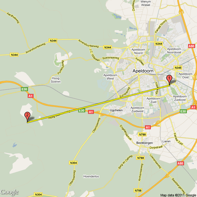
Link overview
This image shows thelink from site 1 to site 2.
Sites
This row shows all geographical information about the Sites that are used in this Link.
PI1APA (1)
| Latitude |
52.201564 |
° |
| Longitude |
5.992506 |
° |
| Ground elevation |
13.01 |
m |
| Antenna height |
2.00 |
m |
| Azimuth |
255.44 |
° |
| Tilt |
0.21 |
° |
|
(2) PI1APK
| Latitude |
52.176202 |
° |
| Longitude |
5.833987 |
° |
| Ground elevation |
64.44 |
m |
| Antenna height |
2.00 |
m |
| Azimuth |
75.31 |
° |
| Tilt |
-0.31 |
° |
|
The following variables are used:
| Variable |
Comment |
| Site |
Site name of site 1 (Left) Has a link to new tab with a Google Map and the site located on it. |
| Latitude |
Latitude in degrees.decemal-degrees |
| Longitude |
Longitude in degrees.decemal-degrees |
| Ground elevation |
Local ground height in meter above sea level (ASL) |
| Antenna height |
Antenna height above ground level in meters |
| Azimuth |
Heading of the antenna in degrees |
| Tilt |
Tilt of the antenna in degrees. 0 degrees is level. |
Radiosystem
The Radiosystem shows relevant information about the radio components of teh Link. These variables are used in the linkbudget.
Radio system
| TX power |
20.000 |
W |
| TX line loss |
3.00 |
dB |
| TX antenna gain |
6.00 |
dBi |
| RX antenna gain |
2.00 |
dBi |
| RX line loss |
0.50 |
dB |
| RX sensitivity |
0.50 |
μV |
|
The following variables are used:
| Variable |
Comment |
| TX power |
Transmitter power in Watt |
| TX line loss |
Losses between transmitter and antenna in dB |
| TX antenna gain |
Gain of the TX antenna in dbi |
| RX antenna gain |
Gain of the RX antenna in dBi |
| RX line loss |
Losses between the antenna and the receiver in dB |
| RX sensitivity |
RX sensitivity expressed in μV |
Propagation
The losses of propagation are here displayed.
Propagation
| Free space loss |
96.65 |
dB |
| Obstuction loss |
46.81 |
dB |
| Forest loss |
2.86 |
dB |
| Urban loss |
5.98 |
dB |
| Statistical loss |
5.72 |
dB |
| Total path loss |
158.02 |
dB |
|
The following variables are used:
| Variable |
Comment |
| Free space loss |
Free space loss in dB between Site 1 and 2 |
| Obstuction loss |
Loss as a result of objects that apear within the fresnel zone and cause obstruction |
| Forest loss |
Loss as a result of clutter with the type Forest that apear within the fresnel zone |
| Urban loss |
Loss as a result of clutter with the type Urban that apear within the fresnel zone |
| Statistical loss |
Statistical Loss  |
| Total path loss |
Sum of all losses |
Performance
Performance
| Distance |
11.168 |
km |
| Frequency |
146.000 |
MHz |
| Equivalent Isotropically Radiated Power |
39.905 |
W |
| System gain |
160.53 |
dB |
| Required reliability |
70.000 |
% |
| E field |
8.49 |
dBμV/m |
| Received Signal |
-110.51 |
dBm |
| Received Signal |
0.67 |
μV |
| Received Signal |
2 |
S-Unit |
| Fade Margin |
2.51 |
dB |
|
The following variables are used:
| Variable |
Comment |
| Distance |
Distance between Site 1 and Sit 2 in Km |
| Frequency |
Frequency in MHz |
| Equivalent Isotropically Radiated Power |
Eirp in watt |
| System gain |
System gain in dB |
| Required reliability |
required reliability of the link in % |
| E field |
Fieldstrength in dBμV per meter |
| Received Signal |
received signale in dBm (50 ohm) micro volt (μV) or S-Units |
| Fade Margin |
Margin available to overcome fading in dB |
Sponsors
Some links to make teh sponsors happy.
Map
A map that displays the link
The color of the line displays the quality of the link.
- Green: The fading margin is above the treshold
- Yellow: The fading margin is below the treshold
- Red: Received signal is below the receive sensitivity of the receiver.
|

